The design and operation of 240-5000 V systems, service continuity, personnel and equipment safety are the most important aspects in industrial systems. The use of...
Download as PDFThe design and operation of 240-5000 V systems, service continuity, personnel and equipment safety are the most important aspects in industrial systems. The use of thehigh-resistance grounded (HRG) system can provide a safe, reliable and economic system for 240-5000 V networks.
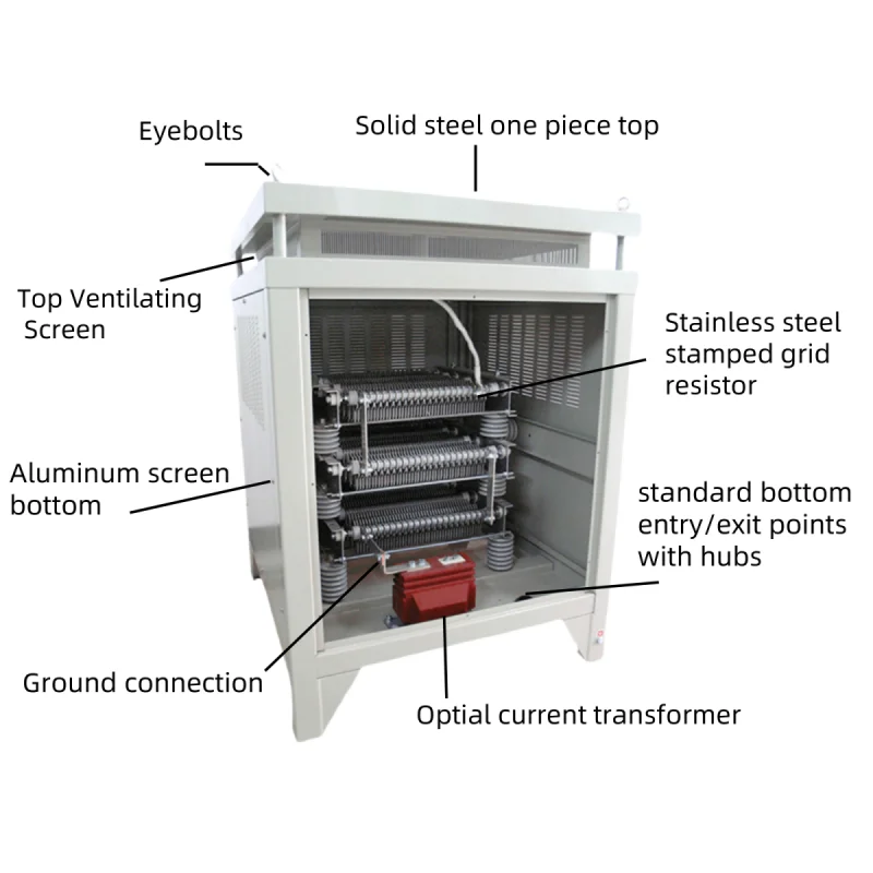
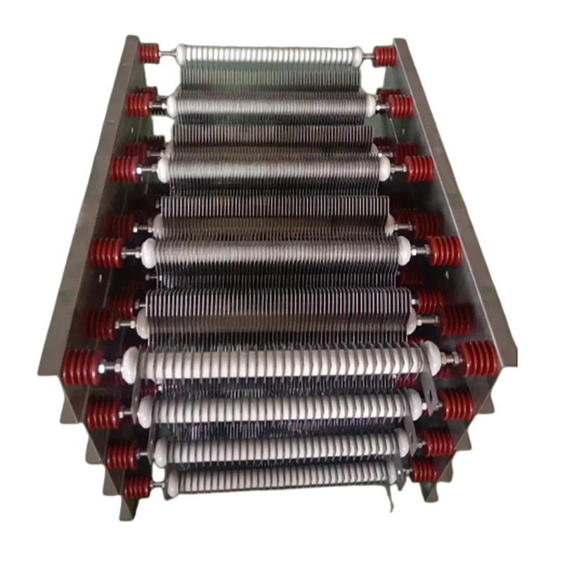
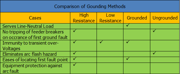
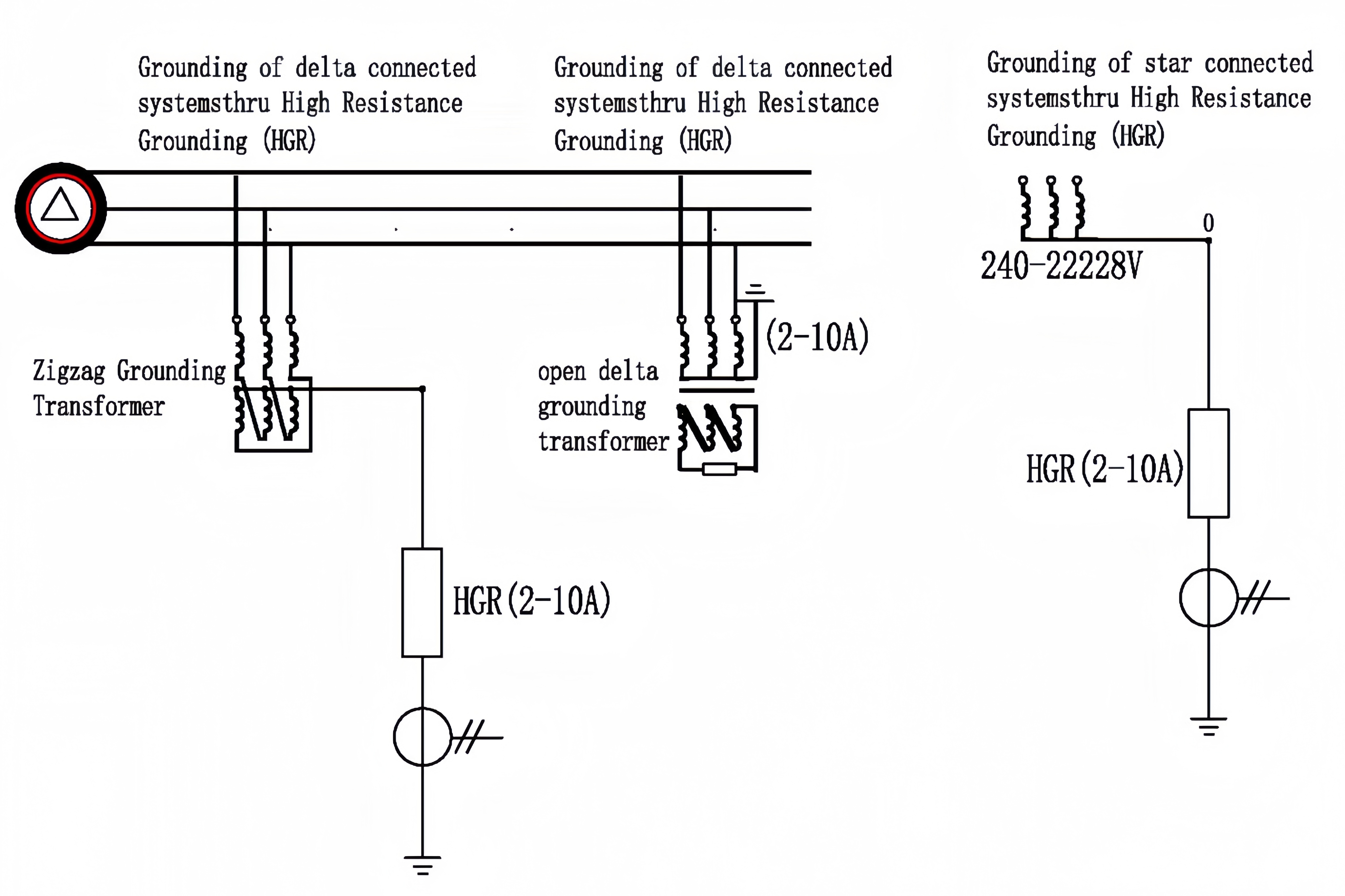
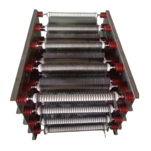
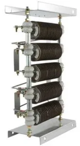
HRG systems limit the fault current by placing high resistance between neutral point of transformer (or generator) and ground. As it is not possible to locate the fault point in delta connected systems, an artificial neutral point is created and delta connected system can be grounded. This allows a fault current of a few amperes thus locating the fault point gets easy. When the neutral point is grounded through high resistance, both continuity of operation is provided during fault condition and sufficient current (typically between 2 A and 10 A) flow is provided for ease of locating the fault point.
Approximate phase to earth fault current in 240-5000 V networks are:
Solidly grounded systems : 1000-6000 A
Low resistance grounded systems: 100-1000 A
High resistance grounded systems: 2-10 A
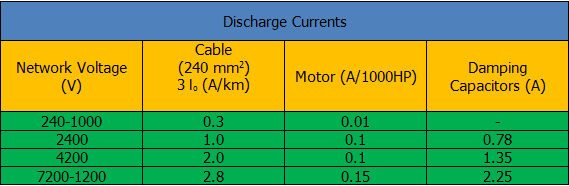
Ungrounded (or delta) cable system: 0.3-2.8 A/km: 2-10 A
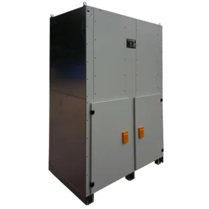
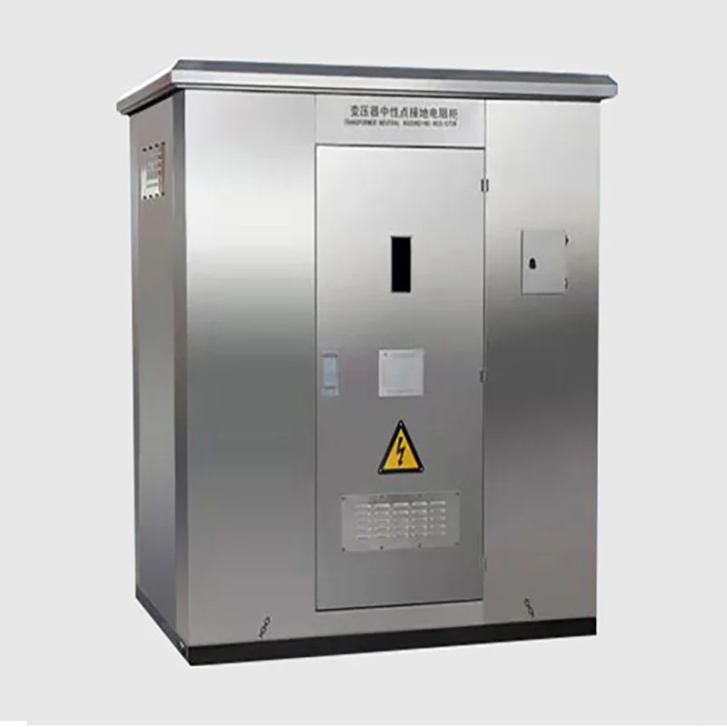
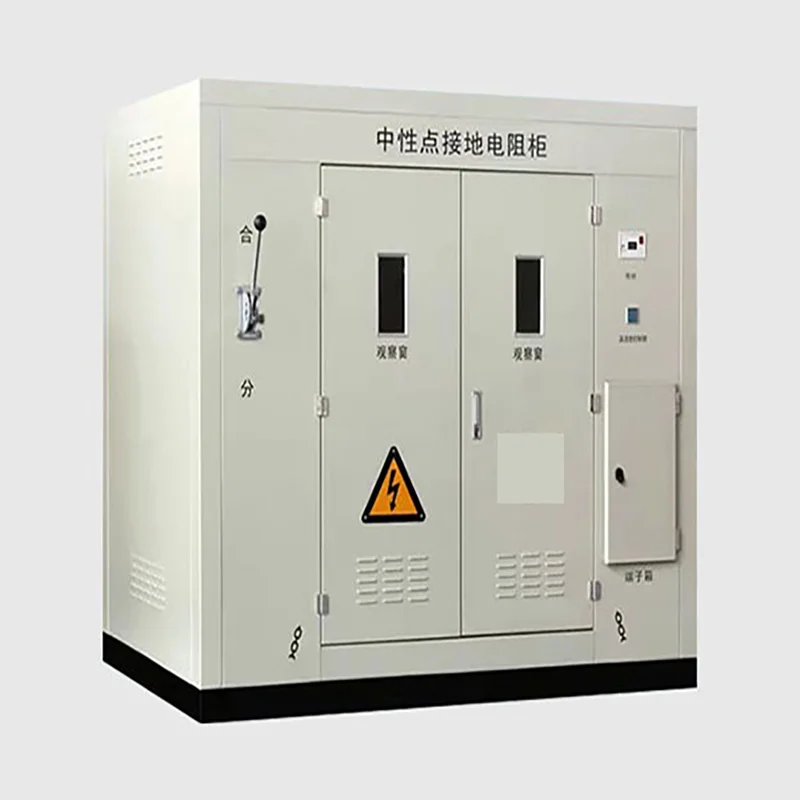
High Resistance Neutral Grounding Devices General Features:
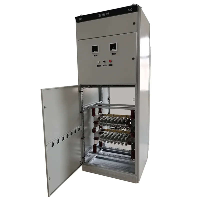
0-10 A analog ammeter, 0-250 V analog voltmeter with setting on panel
Automatic door switch for power shut down
Test button to indicate fault
Green light for normal conditions
Intermittent alarm and red light during ground fault
Pulse/Normal Selector switch to magnify current and intermittent pulse during ground fault
Auxiliary free contacts at pulse and alarm position during fault
Dimensions (LxWxH)= 60 x 60 x 180 cm (Other enclosure types available on demand)
Suitable for 240-5000 V three phase systems
Optional data logging
Usage:
While locating the ground contact point of phase and ground, a fault current that is limited to approximately 2A, generating approximately 10A pulses (approx. 1 second on, 1 second off) provides ease of measurement. Thus using short time pulses is the common application in HRG systems today.
Measurements are generally taken by analogue and wide clamp ammeters. The clamp ammeter outside the phase cable is traced until the pulse current disappears on the analogue display.
High Resistance Grounding Systems are economical and practical choice especially for systems under 5000 Volts.
As zero sequence currents (3Io) flow thru neutral point due to line capacitance of cables, HGR alarm level is set to a point that is greater than 3Io.







![GROUNDING TRANSFORMERS [ZN (ZIGZAG), ZNYN, YND(OPEN), II0]](https://mfrdo.com/wp-content/uploads/2026/08/1-250513155325564-300x300.webp)