Many medium voltage faults start silently. The insulation on the cable breaks down, the motor winding shifts, and a single phase connects to the ground. What comes next is determined many years ago by the decision to use a specific method of connecting the neutral point to the ground. If chosen correctly, the fault becomes a trivial event recorded in the relay. If chosen poorly, you can expect burnt cores, tripped feeders, and a stopped production line. Our neutral earthing equipment allows you to make such decisions. This is an explanation of the various solutions, ways to choose between them and questions to ask a supplier.
We manufacture five series of neutral earthing equipment for electrical networks with voltages ranging from 6 kV to 35 kV.
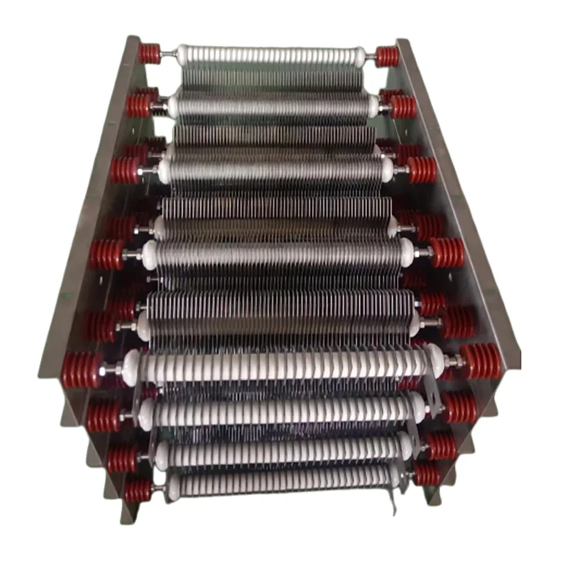
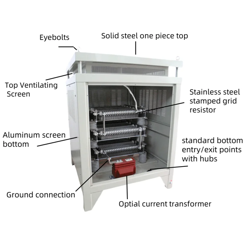
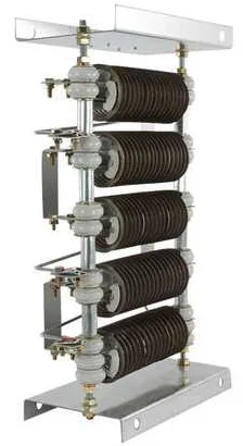
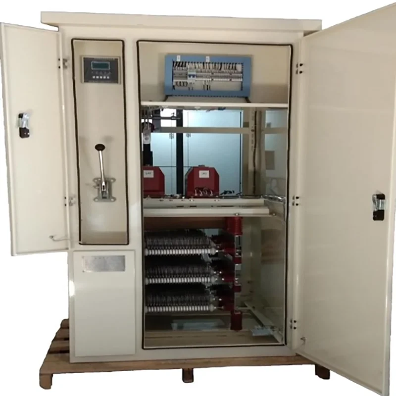
A resistor works as a limit on fault current. It is placed between the neutral point and the ground, and limits any earth fault current to a predetermined level between 10 A and 1000 A. The heat is absorbed by stainless steel or alloy grids. The power range varies between 10 seconds and permanent operation.
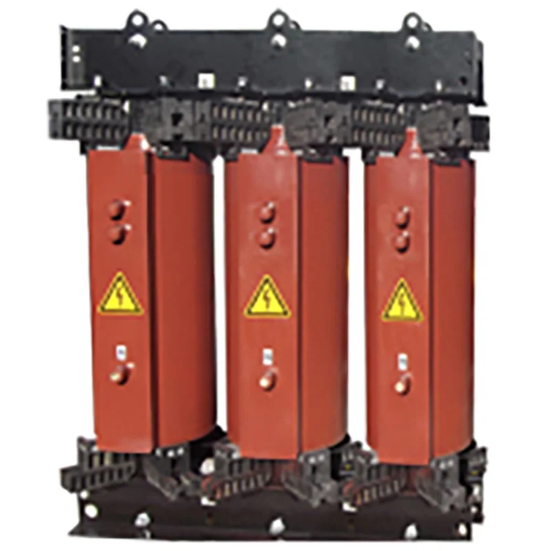
Delta-connected systems do not offer any neutral to ground. Zigzag or star-delta grounding transformers help by creating a neutral point. During normal operation conditions, it will draw nothing, but in case of a fault, it will provide zero-sequence current an easy route to ground.
Arc suppression coils are tuned inductors that cancel out capacitive currents with network capacitance. This way, the current through them cancels out the capacitive current, and the arc often extinguishes even without breaker interruption. The turn-adjustment type alters its inductance in steps by tapping on the winding, while the bias magnetic type changes it in a smooth manner due to a DC-controlled core.
Fault current limitation to about 5 to 10 A practically does not harm the fault point. Generators and motors benefit from this system the most since it reduces the need for rewinding the stator lamination.
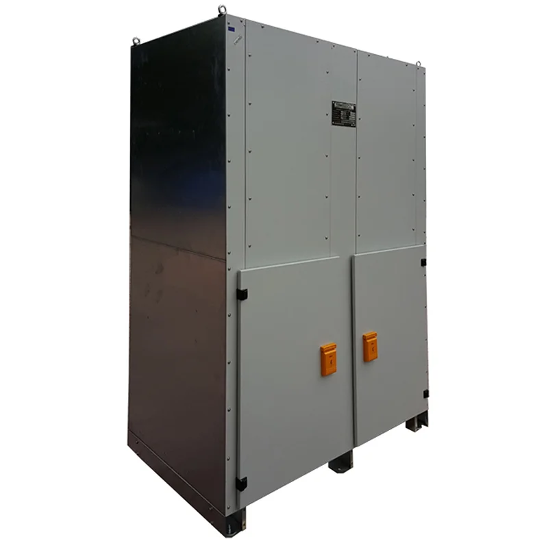
For generators, we put it all together in one enclosure: grounding transformer, secondary resistor, relay, isolator, and metering. This equipment is factory assembled and pre-wired and tested; site installers simply need to wire up the cables. Very few neutral earthing equipment systems are plug-and-play like these.
There are three critical considerations when deciding on neutral earthing equipment. How long are your cables? How sensitive is the equipment you have installed? Can the plant handle a shutdown?
| Your network | What to fit | Why it works |
|---|---|---|
| Short cables, small industrial plant | Low-resistance grounding resistor | Clear fault signal, fast tripping |
| Generator or large motor | High-resistance grounding device | Minimal burn damage |
| Delta system, no neutral | Grounding transformer with resistor | Creates the missing neutral |
| Long cable network, high capacitive current | Arc suppression coil | Many faults clear on their own |
| Overhead lines at 35 kV | Bias magnetic coil | Automatic tuning, fewer outages |
For those networks which lie in between these classifications, our engineers undertake their modelling and suggest MV neutral earthing solutions suitable for the current load conditions and future growth. Well-matched neutral earthing systems also simplify relay settings in the process.
Voltage classes include 6, 10, 20 and 35 kV, while fault current ratings range from 5 A to 1000 A. Rated times include 10 seconds, 60 seconds or continuous operation. Materials used as resistor elements include stainless steel and alloy, while enclosures have ratings from IP23 to IP55. Operating temperature ranges from -25 °C to +50 °C. Coils are adjustable over a wide range from about 10 per cent to 100 per cent of rated current. Our designs comply with IEEE 32 and IEC 60076-6. Share your fault study with us, and we will specify your neutral earthing equipment requirements.
Grounding cubicles play an integral part in protecting the stator windings from the harsh earth-fault currents. Power station substations use resistors and grounding transformers to provide a proper neutral to the distribution feeders. Steel, cement, chemical and paper mills use neutral earthing equipment to withstand small faults without stopping the process line. Mines and ports with long cables and large motors have to have fault limiting equipment that is reliable underground as well as on the quay side. Solar and wind farms use delta-connected collectors, and hence they require a grounding transformer for a ground reference point. In urban areas, arc suppression coils function within the neutral earthing systems to reduce outages in those areas which are critical to continuity.
Catalogues rarely match the real network, and hence we start with a survey. Our engineers determine capacitive current, evaluate the compatibility of relays, and select resistance or inductance suitable for your protection scheme. Our hardware is also customizable with stainless and galvanised enclosures, indoor/outdoor installation, CT/VT arrangements, motor disconnectors, temperature sensors, and SCADA connectivity. Large projects will be delivered with drawings, factory test reports, and commissioning instructions.
All our efforts focus on just one field, and we do it well. Being an unbiased earthing equipment maker, we subject all our products to type-testing and routine testing to comply with the international norms, have a short lead time and properly document our projects. No matter whether you require one resistor or a complete set of MV neutral earthing solutions for your substation, you will talk with our experts.
Look at capacitive fault current first. Short-cable networks usually do well with a resistor, large cable networks lean toward an arc suppression coil, and generators suit high-resistance grounding. Send us your network data, and we will name the best-fit neutral earthing equipment.
A grounding transformer provides one. Connected to the bus, a zigzag or star-delta unit creates an artificial neutral. Add a resistor to that neutral and you decide exactly how much fault current flows.
The earthing method determines fault current size, and that determines how sensitive relays can be. Resistor earthing gives a strong, easy-to-read signal for standard earth-fault relays. Compensated networks need directional or wattmetric relays. Always run relay calculations alongside a neutral earthing system study.
Often, yes. Coils and high-resistance devices let the network operate for a limited time while crews locate the fault, as long as insulation can handle the higher phase-to-earth voltage. Your choice of neutral earthing equipment decides this: low-resistance systems usually trip the faulty feeder straight away.
Yes. We can supply neutral earthing equipment such as transformers, resistors, coils, switches, current transformers and relays as one coordinated package, tested together. Buyers like these MV neutral earthing solutions because ordering, installation and commissioning become simpler.